Zero Loss Drain Valve


Zero Loss Drain Valve
Advantages:
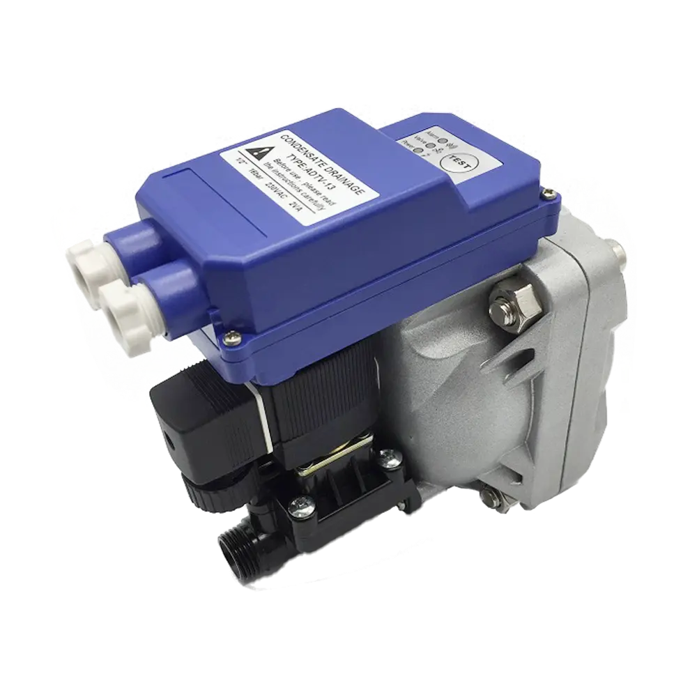
ANKA liquid level control condensate automatic drain valve designed for condensate discharge in the compressed air network. It adopts capacitive electronic liquid level sensor detection, single-chip program control, suitable for all kinds of air compressors, compressed air tanks, and air dryers, air filters, and pipes, etc.
details

Working Principle
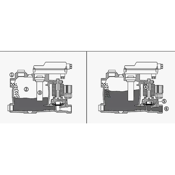
The figure shows that the condensate flows into the condensate drain through inlet ① and accumulates in the chamber ②. The capacitance sensor ③ continuously detects the liquid level and signals the control part when the liquid fills the chamber. Then, pilot valve ④ is activated, and diaphragm valve ⑤ opens drain port ⑥ to discharge condensate. When the condensate in the condensate drain is drained, the drain port will be closed quickly, which will not cause the loss of compressed air.
Detail & Installing
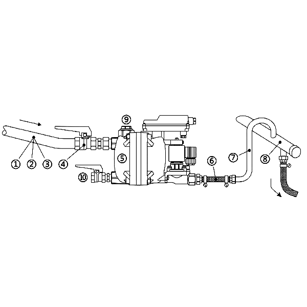
1. The inlet pipe ①should be continuously inclined downward > 1% to make the condensate flow into the water storage tank,
2. The minimum diameter of input pipe② and connector ④is 1 / 2” (inner diameter > 15mm) and large pipe shall be selected as far as possible to reduce resistance
3. Small filter and U-shaped pipeline can not be installed before the inlet ③ , which will affect the self flow performance of condensate.
4. Only large diameter ball valve or gate valve or butterfly valve can be used at the inlet④, and sufficient opening degree shall be ensured.
5. The minimum working pressure of water storage tank⑤ is 0.8bar or 1.6bar (see the label for details).
6. Drainage pressure hose ⑥should be selected as far as possible to facilitate installation.
7. The minimum pressure increase of 0.1bar is required for every 1m rise of the drainage outlet pipe⑦, and the rising section of the output end is not more than 5m!
8. The minimum diameter of the drainage header⑧ is 1 “, and 1% downward tilt can reduce the drainage resistance.
9. The spare nozzle⑨ can be used for vertical installation or large diameter pipe, and can also be used as return pipe.
10. The drain outlet⑩ can be installed with ball valve as manual sewage discharge or as heater installation port.
Remarks: when the condensate automatically flows into the water storage tank or the return
producing PET plastic containers and bottles in all shapes.

Technical Specification
| Model | AD-13 | AD-14 |
| Inlet port size | 2*G1/2″ | 2*G1/2″+ G3/4″ |
| outlet port size | G1/2″ | G1/2″ |
| WorKing tempreture | (1-60)℃ | (1-60)℃ |
| MAX air compressor | 30m³/min | 130m³/min |
| Max freeze dryer | 60m³/min | 260m³/min |
| Max filter | 300m³/min | 1300m³/min |
| Voltage | 220VAC/110VAC/DC24V | 220AC/110AC/DC24V |
| Working pressure | 0.8-16Bar | 0.8-16Bar |

